Update · 24 August 2026
Upgrading the design
Seven changes landing in the next batch — a phase-shift laser module, a fully embedded PCB, a higher-precision tilt sensor, an MJF-printed case and more.
I've taken a short break from manufacturing to upgrade the design and introduce some improvements based on user feedback. Specifically, these include:
A new generation of laser module
The new module calculates distance from the phase shift of the reflected light, rather than time of flight. The result is significantly greater range and much faster readings.
A fully embedded PCB
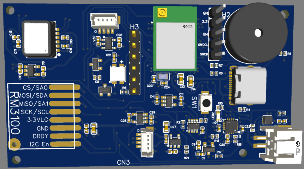
The original DiscoX was built from an array of commercially available breakout boards socketed onto a custom PCB. This made it easier to design conceptually, as most of the hard engineering work had already been done — but it also had major drawbacks. It made the PCB much larger than it needed to be, with more points of failure, and it made the electronic design difficult to optimise, as I was constrained by what the breakout boards were capable of.
So I went back to the drawing board and made a fully pick-and-placed board with the exact components I needed to make the DiscoX work the way I wanted.
A high-precision tilt sensor
The DiscoX already used a best-in-class compass sensor for direction (the RM3100), but the tilt sensor had room for improvement. I've since upgraded the board to use an SCA3000, which provides a much lower noise floor and more accurate readings.
A Multi Jet Fusion 3D-printed case
The cases for the original DiscoX were 3D printed on a hobby printer and required an internal coating of epoxy to prevent water ingress. The newer cases are made using commercial-grade printers that fuse layers of nylon powder to form parts, followed by a vapour-smoothing process to create a sealed finish. This produces cases of comparable quality to injection-moulded parts.
Custom membrane buttons
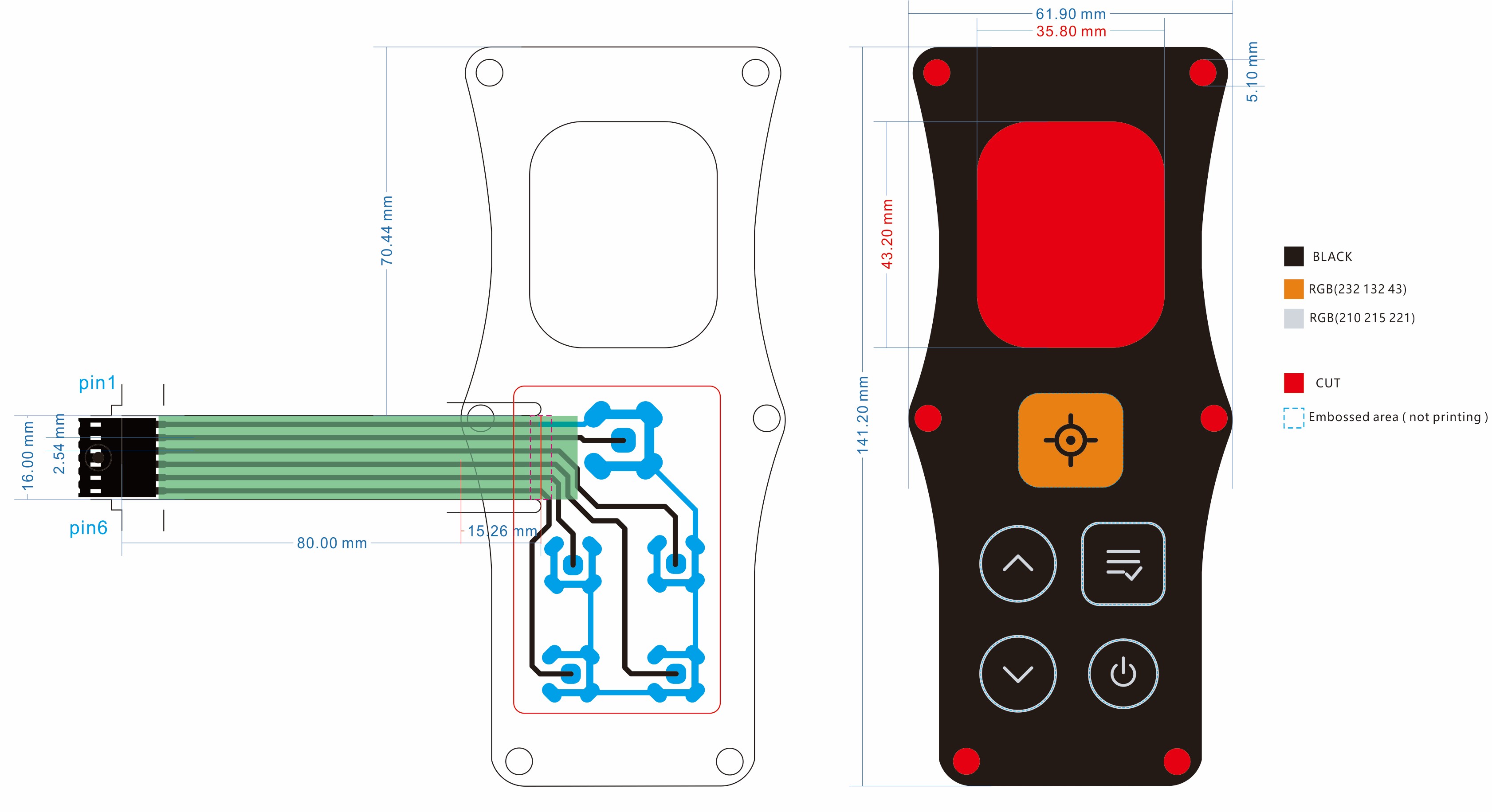
The biggest complaint I had from users was that the buttons weren't very intuitive — a consequence of being limited to what I could buy off the shelf. I now have a fully custom-made membrane button cover that provides a more ergonomic, easy-to-use interface.
A larger screen
I've increased the screen size to 1.5″, making it easier to read the menu and see readings on the display.
A multi-tone buzzer
Previously I used the buzzer built into the laser module, which only had a single tone — making it harder for users to distinguish between legs, splays and anomalous shots. I've since upgraded to a larger 8-bit buzzer capable of many different tones.
What's next
I should soon have enough devices to fulfil any pre-orders — I'm currently waiting on the final few parts to come through before going into production. I'm hoping to have a more streamlined supply chain in place for future batches, now that I'm fairly settled on this design.